


Reasons and Solutions for Gear Pump Not Feeding
2026-02-09 15:47:27
The reasons for gear pumps failing to draw material (also known as "suction failure" or "cavitation") are diverse and require systematic troubleshooting. Below is a detailed analysis of the causes and solutions. Core issue: The pump inlet cannot generate sufficient vacuum (negative pressure) to overcome resistance and "pull" the material in, or cavitation occurs inside the pump. 1. Main Causes and Solutions A. Reasons related to materials and pipelines Material viscosity issue · Cause: The material has excessively high viscosity (e.g., thickening at low temperatures), resulting in extremely poor fluidity and excessive flow resistance in the suction pipeline. · Solution: · Preheat or maintain the temperature of the material to reduce its viscosity. Consider using positive pressure feeding (such as pressurizing the storage tank) or switching to pump types more suitable for high viscosity (such as screw pumps or plunger pumps). 2. Feed pipeline issue · Reason: · Pipe blockage: The filter, inlet valve, or the pipe itself is obstructed by foreign matter or condensation. · The pipe diameter is too small or too long: resulting in excessive frictional resistance. Pipeline air leakage: Loose connections, hoses, or flange seals allow air to be drawn in, disrupting the vacuum. · Excessive suction lift: The vertical distance between the pump and the liquid source is too great (gear pumps have limited self-priming height, generally recommended to be within 5-6 meters, with lower values allowed for higher viscosity). · Solution: · Thoroughly inspect and clean the inlet filter, valves, and pipelines. · Shorten the length of the suction pipe, increase the pipe diameter (the suction pipe diameter should generally not be smaller than the pump inlet diameter), and reduce the number of elbows. · Check the sealing of all connections, tighten or replace the seals. Apply soapy water at suspicious points to test for air suction. Reduce the installation height and minimize the suction lift. Alternatively, opt for submerged or self-priming (i.e., with positive head at the pump inlet) installation. 3. Tank or liquid source issues · Reason: · Low liquid level: The inlet pipe is exposed above the liquid surface, drawing in air. · Blocked vent hole: The vent hole of the sealed storage tank is blocked, creating a vacuum that prevents material from flowing out. · Solution: Ensure the feed pipe opening is always submerged below the liquid surface (typically requiring at least 0.5 meters). · Inspect and clear the vent holes of the storage tank to ensure atmospheric pressure can act on the liquid surface.
B. Reasons related to the pump itself
1. Incorrect rotation direction
Reason: Incorrect motor wiring causes the pump to rotate in reverse, resulting in no material intake and potential pump damage.
Solution: Immediately stop the machine, inspect and correct the motor rotation direction.
2. The pump is not primed (during initial startup or after maintenance)
Reason: The gear pump, especially new or overhauled pumps, has an empty chamber without any medium to form a seal and provide lubrication, making self-priming impossible.
Solution: The pump must be primed by filling the pump chamber with the medium to be conveyed from the outlet or a dedicated filling port, ensuring all air is expelled.
3. Excessive wear or clearance
Reason: Excessive wear clearance between the gear end face, tooth top, and pump housing causes severe internal leakage, preventing the formation of an effective vacuum zone at the inlet.
Solution: Disassemble and inspect. If wear exceeds the limit, replace the gear, shaft sleeve, or side plate, or directly replace the pump head.
4. Shaft seal damage
Cause: Severe damage to mechanical or packing seals, resulting in significant air intake from the shaft seal. Solution: Replace the shaft seal. Ensure correct installation methods and inspect the shaft sleeve for wear grooves.
C. Reasons related to operational conditions
1. RPM issue
Reason: The rotational speed is too low (e.g., when using a frequency converter, the frequency setting is too low), and the pump's displacement is too small to generate effective suction.
Solution: Increase the pump speed to the rated range. Note: Excessively high speed may also exacerbate cavitation and wear.
2. Medium temperature
Reason: Excessive temperature causes volatile components in the medium to vaporize or increases the saturated vapor pressure, easily generating bubbles (cavitation) in the low-pressure inlet zone.
Solution: Cool the inlet pipeline or adjust the process conditions to prevent the medium from vaporizing at the pump inlet.
II. Systematic Troubleshooting Steps (From Simple to Complex)
1. Step 1: Conduct an on-site visual inspection to confirm the correct rotation of the motor. Check whether the tank liquid level is sufficient. Touch the inlet pipeline to feel for suction or vibration (severe cavitation will cause intense shaking of the pipeline). Listen for sounds: "whistling" or "popping" noises usually indicate air leakage or cavitation; dry grinding sounds suggest the pump is running dry or in an empty state.
2. Step 2: Check that the pipeline and valves are fully open and the inlet valve is open.
Inspect and clean the inlet filter. Conduct a gas tightness check on the inlet pipeline (especially the hose section).
3. Step Three: Pump Priming and Air Venting
Ensure the pump cavity and inlet pipeline are filled with liquid. Loosen the vent plug on the outlet or pump body to purge air.
4. Step 4: Inspect the pump itself
If the above steps are ineffective, it may indicate damage to internal pump components. The pump should be shut down and disassembled to inspect the wear conditions of the gear, shaft sleeve, side plate, shaft seal, and other parts.
3. Preventive Measures
Proper Installation: Follow the "coarse, short, straight" principle for installing imported pipelines, and opt for positive pressure feeding whenever possible.
Proper maintenance: Regularly clean the filters, inspect the pipeline seals, and check the wear of the pump.
Standard operating procedures: No idling is permitted. Ensure the pump is primed before starting, and avoid operation under extreme temperatures or viscosities.
Selection matching: During procurement, ensure to provide suppliers with accurate medium properties (viscosity, temperature, corrosiveness, etc.) and operating conditions (flow rate, pressure, suction lift, etc.) to guarantee proper gear pump model matching.
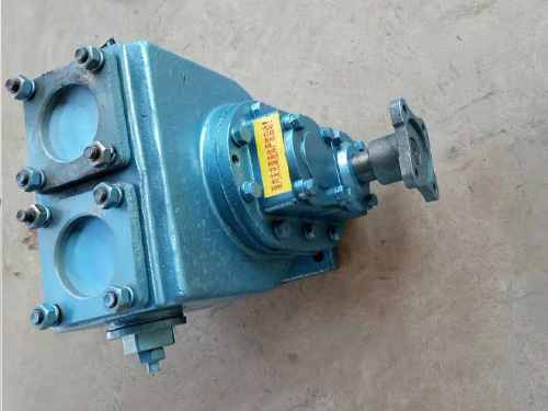
The YHCB high flow pump has the characteristics of large flow rate, high head, small settli...
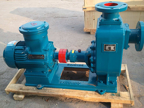
The CYZ centrifugal pump adopts an axial return liquid pump body structure, which is compos...
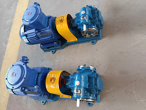
Copper gear pump (KCB type) is suitable for conveying lubricating oil or other liquids with...
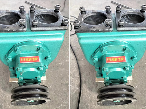
The car mounted circular arc gear pump can be installed on the car and driven by the output...